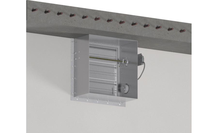
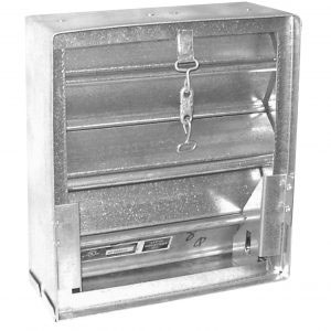
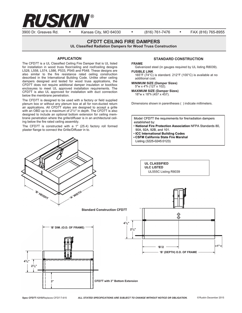
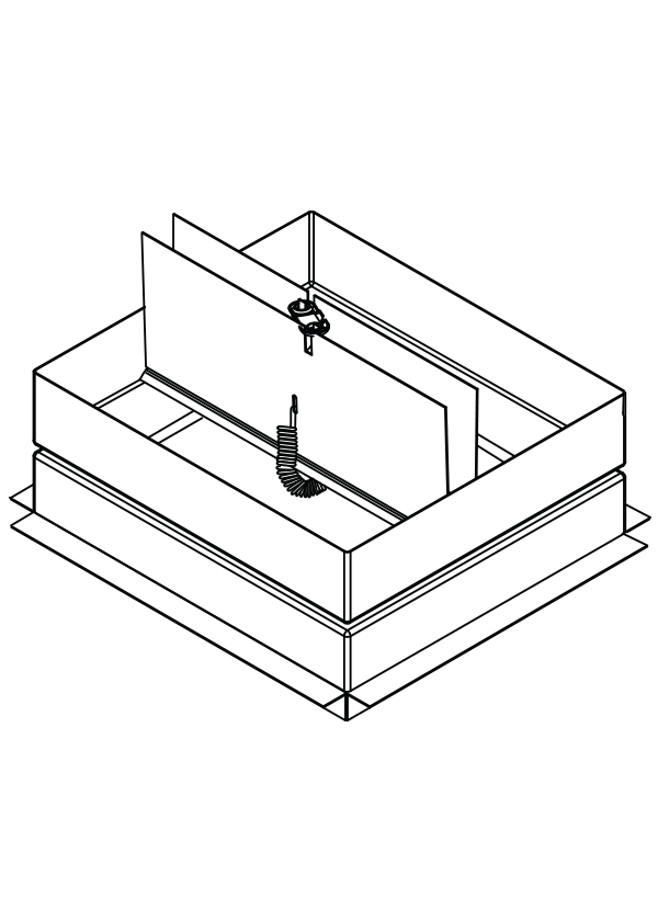
Ceiling radiation dampers shall comply with ul 555c and shall be installed in accordance with the manufacturer s installation instructions in the fire resistive ceiling membrane of floor ceiling and roof ceiling assemblies where required by the building code.
Ceiling fire damper installation.
Equipped with fusible link at no extra charge.
These installation instructions apply to a 3 hour rated ceiling radiation dampers aka ceiling dampers mounted in a ceiling with supports from 1 a ceiling grid system 2 ductwork above or 3 structure above.
As with all joints contractor must seal duct collar connection in field after installation.
Sleeve is not required to be centered but can rest on the bottom of the opening.
Fire damper sleeve clearance within wall floor opening i.
The industrial grade backdraft dampers offer rugged construction and heavy gage materials to withstand the high velocities and back pressures associated with heavy duty installations.
Perimeter angles shall overlap the wall floor by a minimum of 1.
Foot on height and width of sleeve to a maximum of 1 1 2 e g.
This allows the consumer more access to the damper in the event that maintenance needs to be performed or the fuse link requires replacing.
From light operations to heavy duty industrial applications ruskin provides the perfect backdraft damper.
The cfd2 is a ul555c classified ceiling fire damper.
Operated by a fuse link these dampers come spring loaded and are available with an easy access assembly.
Tests that apply to ceiling dampers intended for installation in fire resistance rated floor ceiling and roof ceiling assemblies.
The investigation of ceiling dampers for use in floor ceiling or.
In maximum are allowable.
Ceiling openings up to a 24 x 24 610mm x 610mm 576 sq.
A 36 x 20 fire damper sleeve will have an opening of.
With attention to the following requirements the ceiling grid system provides all required support for installation of lay in style ceiling dampers and the grilles.
They are used to protect hvac openings in fire rated horizontal ceiling assemblies.
Among other tests ul 555c includes a fire endurance test that utilizes the same time temperature curve used in ul 263.
Fire and heat protection where hvac components penetrate the ceiling membrane.
Maximum size limits of each individual ceiling damper model must be observed.
Minimum clearance shall be.
Each type of damper support system is described with damper being mounted in conjunction with various air devices.
1 8 10 expansion joint per linear foot ii.
Listed clearance requirements are 1 8 per linear foot unless stated otherwise.
Damper 47 3 4 x 47 3 4 collar 48 x 48 opening 49 1 2 x 49 1 2.


